Updated with NEC inverter definitions.
Source Link
LShaver
  • 11.9k
  • 6
  • 32
  • 83

The problem -- you have grid-tied (or gridutility-following)interactive inverters

GridUtility-tieinteractive inverters (also known as grid-tie or grid following) use phase-locked loop (PLL) control to match the frequency and phase of their output signal to what they detect on the grid. In doing this they also affect the grid, but these changes are barely perceptible (ripples in an ocean). But if the grid is absent, the changes that each inverter implements would have a greater effect (ripples in a teacup), causing cascading fluctuations on the inverter network, which feeds back to the input of each inverter. As the changes amplify, the PLL will become unstable and the inverter will shut down. The UL 1741 limits* are programmed to shut the inverters down before they reach this technical limit, but either way, if the input ac signal starts fluctuating too quickly, the inverters will shut down.

Solution one: off-gridStandalone inverters with communication

OffStandalone or off-grid inverters (that you'd use for a camper, boat, or remote cabin) develop and sustain their own 60 Hz signal. There's a chance you could install a single off-gridstandalone inverter in your system (perhaps at the ???? location, drawing off the battery bank), and the gridutility-tiedinteractive inverters would be fooled into following it.

  1. The signal probably won't be "stiff" enough. Standard off-gridstandalone inverters aren't designed to work in tandem with gridutility-tiedinteractive inverters, so the signal they provide is unlikely to be stiff enough to "fool" them.
  2. GridUtility-tiedinteractive inverters are current sources and could cause runaway voltage without sufficient load. Standard gridutility-tiedinteractive inverters are designed to push a steady current out by raising their output voltage. When connected to the grid, there's a huge sink for this current to go to, so they don't have to raise the voltage much at all. But in an off-grid situation, if they run out of load (batteries are charged and nothing is using power), they might increase the voltage until something breaks. For many inverters, anti-islanding protection is the only way to prevent this -- they can't be online without the grid as a sink, so this problem won't occur. Others will stop producing all power if the voltage goes too high (as a backup to anti-islanding protection), while others have the ability to limit the output voltage and continue producing (less) power.

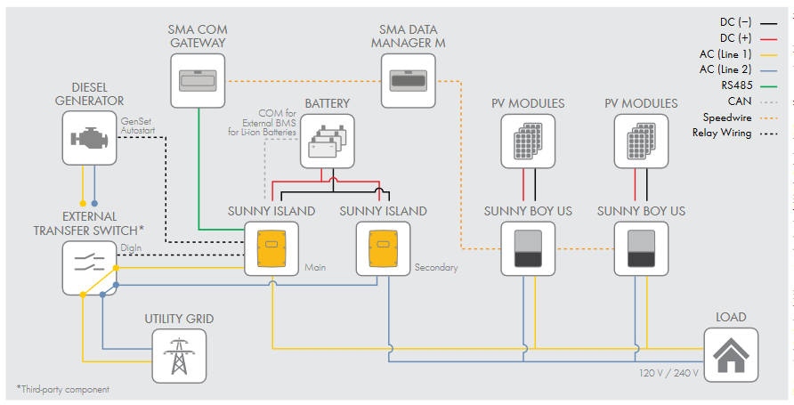
The Sunny Island inverter from SMA is an example of an off-grida standalone inverter that can do this with other SMA inverters. You can see the communication interface in the diagram below:

Solution two: an ac-coupled system with a grid-forming multimode inverter

These inverters are called grid forming because they create a stiff enough signal to provide support for grid following inverters. Multimode refers to their ability to be utility-interactive when connected to the grid, and standalone otherwise.
The problem -- you have grid-tied (or grid-following) inverters

Grid-tie inverters use phase-locked loop (PLL) control to match the frequency and phase of their output signal to what they detect on the grid. In doing this they also affect the grid, but these changes are barely perceptible (ripples in an ocean). But if the grid is absent, the changes that each inverter implements would have a greater effect (ripples in a teacup), causing cascading fluctuations on the inverter network, which feeds back to the input of each inverter. As the changes amplify, the PLL will become unstable and the inverter will shut down. The UL 1741 limits* are programmed to shut the inverters down before they reach this technical limit, but either way, if the input ac signal starts fluctuating too quickly, the inverters will shut down.

Solution one: off-grid inverters with communication

Off-grid inverters (that you'd use for a camper, boat, or remote cabin) develop and sustain their own 60 Hz signal. There's a chance you could install a single off-grid inverter in your system (perhaps at the ???? location, drawing off the battery bank), and the grid-tied inverters would be fooled into following it.

  1. The signal probably won't be "stiff" enough. Standard off-grid inverters aren't designed to work in tandem with grid-tied inverters, so the signal they provide is unlikely to be stiff enough to "fool" them.
  2. Grid-tied inverters are current sources and could cause runaway voltage without sufficient load. Standard grid-tied inverters are designed to push a steady current out by raising their output voltage. When connected to the grid, there's a huge sink for this current to go to, so they don't have to raise the voltage much at all. But in an off-grid situation, if they run out of load (batteries are charged and nothing is using power), they might increase the voltage until something breaks. For many inverters, anti-islanding protection is the only way to prevent this -- they can't be online without the grid as a sink, so this problem won't occur. Others will stop producing all power if the voltage goes too high (as a backup to anti-islanding protection), while others have the ability to limit the output voltage and continue producing (less) power.

The Sunny Island inverter from SMA is an example of an off-grid inverter that can do this with other SMA inverters. You can see the communication interface in the diagram below:

Solution two: an ac-coupled system with a grid-forming inverter

These inverters are called grid forming because they create a stiff enough signal to provide support for grid following inverters.

The problem -- you have utility-interactive inverters

Utility-interactive inverters (also known as grid-tie or grid following) use phase-locked loop (PLL) control to match the frequency and phase of their output signal to what they detect on the grid. In doing this they also affect the grid, but these changes are barely perceptible (ripples in an ocean). But if the grid is absent, the changes that each inverter implements would have a greater effect (ripples in a teacup), causing cascading fluctuations on the inverter network, which feeds back to the input of each inverter. As the changes amplify, the PLL will become unstable and the inverter will shut down. The UL 1741 limits* are programmed to shut the inverters down before they reach this technical limit, but either way, if the input ac signal starts fluctuating too quickly, the inverters will shut down.

Solution one: Standalone inverters with communication

Standalone or off-grid inverters (that you'd use for a camper, boat, or remote cabin) develop and sustain their own 60 Hz signal. There's a chance you could install a single standalone inverter in your system (perhaps at the ???? location, drawing off the battery bank), and the utility-interactive inverters would be fooled into following it.

  1. The signal probably won't be "stiff" enough. Standard standalone inverters aren't designed to work in tandem with utility-interactive inverters, so the signal they provide is unlikely to be stiff enough to "fool" them.
  2. Utility-interactive inverters are current sources and could cause runaway voltage without sufficient load. Standard utility-interactive inverters are designed to push a steady current out by raising their output voltage. When connected to the grid, there's a huge sink for this current to go to, so they don't have to raise the voltage much at all. But in an off-grid situation, if they run out of load (batteries are charged and nothing is using power), they might increase the voltage until something breaks. For many inverters, anti-islanding protection is the only way to prevent this -- they can't be online without the grid as a sink, so this problem won't occur. Others will stop producing all power if the voltage goes too high (as a backup to anti-islanding protection), while others have the ability to limit the output voltage and continue producing (less) power.

The Sunny Island inverter from SMA is an example of a standalone inverter that can do this with other SMA inverters. You can see the communication interface in the diagram below:

Solution two: an ac-coupled system with a grid-forming multimode inverter

These inverters are called grid forming because they create a stiff enough signal to provide support for grid following inverters. Multimode refers to their ability to be utility-interactive when connected to the grid, and standalone otherwise.
added 465 characters in body
Source Link
LShaver
  • 11.9k
  • 6
  • 32
  • 83

tl;dr: Because of how the grid and your inverters work, it's unlikely that there is a solution for your current system. You will either need to set up a communication network with your microinverters and another device, or you will need to set up an ac-coupled system with a centralized battery charger, inverter, and grid disconnect. This will probably require you to replace your microinverters.

Are youI gather you're imagining that "????" is some sort of device that would provide an AC signal to "fool" the inverters into thinking they're seeing an ac signal?, so they could generate power even with the actual grid signal.

The inverters you have are grid-tied inverters. Not only are theyyour inverters required by UL 1741 to stop supplying power when the grid signal disappears, they are technically unable to do otherwise. Consider that you have multiple string inverters. When there's an outage, they wouldn't all detect this simultaneously -- so at least one should continue producing 60 Hz -- in theory, this should be enough to provide a 60 Hz signal for the rest. So why doesn't it work?

The grid provides a "stiff" signal. Short of substations, power plants, or large industrial facilities going offline, load and supply changes will not move the frequency by much. This is fundamental to the droop control algorithm that governs the grid. A large or fast shift in the frequency indicates that an outage is imminent, because the grid is moving outside of the range under which droop control can managebalances loads and sources.

Grid-tie inverters use phase-locked loop (PLL) control to match the frequency and phase of theirtheir output signal to what they detect on the grid. Normally, the grid-tied inverters are following the grid signal, but they'reIn doing this they also causing changes of their own. Withaffect the grid present, but these changes are barely perceptible (ripples in an ocean). But if the grid is absent, the changes that each inverter implements willwould have a greater effect (ripples in a teacup), causing cascading fluctuations on the inverter network, which feedfeeds back to the input of each inverter. If this frequency is changing too fastAs the changes amplify, the PLL will become unstable and the inverter will shut down. The UL 1741 limits* are programmed intoto shut the inverters down before they reach this technical limit, but either way, if the input ac signal starts fluctuating too quickly, the inverters will shut down.

There are two potential solutions to this problem, but either one will may require new microinverters.

Off-grid inverters, that (that you'd use for a camper, boat, or remote cabin,) develop and sustain their own 60 Hz signal. There's a chance you could install a single off-grid inverter in your system (perhaps at the ???? location, drawing off the battery bank), and the grid-tied inverters would be fooled into following it.

  1. The signal probably won't be "stiff" enough. Standard off-grid inverters aren't designed to work in tandem with grid-tied inverters, so the signal they provide is unlikely to be stiff enough to "fool" them.
  2. Grid-tied inverters are current sources and could cause runaway voltage without sufficient load. Standard grid-tied inverters are designed to push a steady current out by raising their output voltage. When connected to the grid, there's a huge sink for this current to go to, so they don't have to raise the voltage much at all. But in an off-grid situation, if they "run out"run out of load -- the batteries(batteries are charged and no onenothing is around using any power --), they might increase the voltage until something breaks. For many inverters, oranti-islanding protection is the only way to prevent this -- they can't be online without the grid as a safety mechanism kicks insink, so this problem won't occur. Others will stop producing all power if the voltage goes too high (as a backup to anti-islanding protection), while others have the ability to limit the output voltage and shuts it offcontinue producing (less) power.

One way around these problems is with a communication interface between inverters. In your case, thatYou would probably mean replacing allneed to check the specification of your microinverters to see if they support this, since the communication protocol isand what other products they could work with. Unfortunately, these systems are not yet standardized and tends to be proprietary (and microinverters are unlikely to, so you may have any sort of communication interface)trouble finding something that works.

In this case, you would utilize a battery inverter/charger that is designed specifically for this application. (Schneider electric and Outback Power are the first two I found where I could easily confirm they work in this fashion, but there are probably many others.)

These inverters are called grid forming because they create a stiff enough signal to provide support for grid following inverters.

In this solution, the inverter/charger can draw from the grid, the batteries, or the solar array, and supply power to the loads, or back to the grid. When the UL 1741 limits kick in, it disconnects from the grid, but continues drawing power from the PV array or the batteries to supply load. It is designed to produce an ac signal sufficient to operate grid-tied inverters, as long as they're rated to operate in an ac-coupled systemas long as they're rated to operate in an ac-coupled system (meaning their voltage output is limited).

*I don't have UL1741 handy, but the limits are defined in IEEE 1547-2018 mirrors it, and gives theseThese ranges asare default settings -- there are situations where an inverter can stay connected outside of these ranges, depending on utility interconnect agreements:

tl;dr: Because of how the grid and your inverters work, it's unlikely that there is a solution for your current system. You will need to set up an ac-coupled system with a centralized battery charger, inverter, and grid disconnect. This will probably require you to replace your microinverters.

Are you imagining that "????" is some sort of device that would provide an AC signal to "fool" the inverters into thinking they're seeing an ac signal?

The inverters you have are grid-tied inverters. Not only are they required by UL 1741 to stop supplying power when the grid signal disappears, they are technically unable to do otherwise. Consider that you have multiple string inverters. When there's an outage, they wouldn't all detect this simultaneously -- so at least one should continue producing 60 Hz -- in theory, this should be enough to provide a 60 Hz signal for the rest. So why doesn't it work?

The grid provides a "stiff" signal. Short of substations, power plants, or large industrial facilities going offline, load and supply changes will not move the frequency by much. This is fundamental to the droop control algorithm that governs the grid. A large or fast shift in the frequency indicates that an outage is imminent, because the grid is moving outside of the range under which droop control can manage loads and sources.

Grid-tie inverters use phase-locked loop (PLL) control to match the frequency and phase of their output signal to what they detect on the grid. Normally, the grid-tied inverters are following the grid signal, but they're also causing changes of their own. With the grid present, these changes are barely perceptible (ripples in an ocean). But if the grid is absent, the changes that each inverter implements will have a greater effect (ripples in a teacup), causing cascading fluctuations which feed back to the input of each inverter. If this frequency is changing too fast, the PLL will become unstable and the inverter will shut down. The UL 1741 limits* are programmed into the inverters before they reach this technical limit, but either way, if the input ac signal starts fluctuating too quickly, the inverters will shut down.

There are two potential solutions to this problem, but either one will may require new microinverters.

Off-grid inverters, that you'd use for a camper, boat, or remote cabin, develop and sustain their own 60 Hz signal. There's a chance you could install a single off-grid inverter in your system (perhaps at the ???? location, drawing off the battery bank), and the grid-tied inverters would be fooled into following it.

  1. The signal probably won't be "stiff" enough. Standard off-grid inverters aren't designed to work in tandem with grid-tied inverters, so the signal they provide is unlikely to be stiff enough to "fool" them.
  2. Grid-tied inverters are current sources and could cause runaway voltage without sufficient load. Standard grid-tied inverters are designed to push a steady current out by raising their output voltage. When connected to the grid, there's a huge sink for this current, so they don't have to raise the voltage much at all. But in an off-grid situation, if they "run out" of load -- the batteries are charged and no one is around using any power -- they might increase the voltage until something breaks, or a safety mechanism kicks in and shuts it off.

One way around these problems is with a communication interface between inverters. In your case, that would probably mean replacing all of your microinverters, since the communication protocol is not yet standardized and tends to be proprietary (and microinverters are unlikely to have any sort of communication interface).

In this case, you would utilize a battery inverter/charger that is designed specifically for this application. (Schneider electric and Outback Power are the first two I found where I could easily confirm they work in this fashion, but there are probably many others.)

In this solution, the inverter/charger can draw from the grid, the batteries, or the solar array, and supply power to the loads, or back to the grid. When the UL 1741 limits kick in, it disconnects from the grid, but continues drawing power from the PV array or the batteries to supply load. It is designed to produce an ac signal sufficient to operate grid-tied inverters, as long as they're rated to operate in an ac-coupled system (meaning their voltage output is limited).

*I don't have UL1741 handy, but IEEE 1547-2018 mirrors it, and gives these ranges as default settings -- there are situations where an inverter can stay connected outside of these ranges, depending on utility interconnect agreements:

tl;dr: Because of how the grid and your inverters work, it's unlikely that there is a solution for your current system. You will either need to set up a communication network with your microinverters and another device, or you will need to set up an ac-coupled system with a centralized battery charger, inverter, and grid disconnect. This will probably require you to replace your microinverters.

I gather you're imagining that "????" is some sort of device that would provide an AC signal to "fool" the inverters into thinking they're seeing an ac signal, so they could generate power even with the actual grid signal.

Not only are your inverters required by UL 1741 to stop supplying power when the grid signal disappears, they are technically unable to do otherwise. When there's an outage, they wouldn't all detect this simultaneously -- so at least one should continue producing 60 Hz -- in theory, this should be enough to provide a 60 Hz signal for the rest. So why doesn't it work?

The grid provides a "stiff" signal. Short of substations, power plants, or large industrial facilities going offline, load and supply changes will not move the frequency by much. This is fundamental to the droop control algorithm that governs the grid. A large or fast shift in the frequency indicates that an outage is imminent, because the grid is moving outside of the range under which droop control can balances loads and sources.

Grid-tie inverters use phase-locked loop (PLL) control to match the frequency and phase of their output signal to what they detect on the grid. In doing this they also affect the grid, but these changes are barely perceptible (ripples in an ocean). But if the grid is absent, the changes that each inverter implements would have a greater effect (ripples in a teacup), causing cascading fluctuations on the inverter network, which feeds back to the input of each inverter. As the changes amplify, the PLL will become unstable and the inverter will shut down. The UL 1741 limits* are programmed to shut the inverters down before they reach this technical limit, but either way, if the input ac signal starts fluctuating too quickly, the inverters will shut down.

There are two potential solutions to this problem, but either one may require new microinverters.

Off-grid inverters (that you'd use for a camper, boat, or remote cabin) develop and sustain their own 60 Hz signal. There's a chance you could install a single off-grid inverter in your system (perhaps at the ???? location, drawing off the battery bank), and the grid-tied inverters would be fooled into following it.

  1. The signal probably won't be "stiff" enough. Standard off-grid inverters aren't designed to work in tandem with grid-tied inverters, so the signal they provide is unlikely to be stiff enough to "fool" them.
  2. Grid-tied inverters are current sources and could cause runaway voltage without sufficient load. Standard grid-tied inverters are designed to push a steady current out by raising their output voltage. When connected to the grid, there's a huge sink for this current to go to, so they don't have to raise the voltage much at all. But in an off-grid situation, if they run out of load (batteries are charged and nothing is using power), they might increase the voltage until something breaks. For many inverters, anti-islanding protection is the only way to prevent this -- they can't be online without the grid as a sink, so this problem won't occur. Others will stop producing all power if the voltage goes too high (as a backup to anti-islanding protection), while others have the ability to limit the output voltage and continue producing (less) power.

One way around these problems is with a communication interface between inverters. You would need to check the specification of your microinverters to see if they support this, and what other products they could work with. Unfortunately, these systems are not yet standardized, so you may have trouble finding something that works.

In this case, you would utilize a battery inverter/charger that is designed specifically for this application. (Schneider electric and Outback Power are the first two I found where I could easily confirm they work in this fashion, but there are probably many others.)

These inverters are called grid forming because they create a stiff enough signal to provide support for grid following inverters.

In this solution, the inverter/charger can draw from the grid, the batteries, or the solar array, and supply power to the loads, or back to the grid. When the UL 1741 limits kick in, it disconnects from the grid, but continues drawing power from the PV array or the batteries to supply load. It is designed to produce an ac signal sufficient to operate grid-tied inverters, as long as they're rated to operate in an ac-coupled system (meaning their voltage output is limited).

*I don't have UL1741 handy, but the limits are defined in IEEE 1547-2018 These ranges are default settings -- there are situations where an inverter can stay connected outside of these ranges, depending on utility interconnect agreements:

Source Link
LShaver
  • 11.9k
  • 6
  • 32
  • 83

tl;dr: Because of how the grid and your inverters work, it's unlikely that there is a solution for your current system. You will need to set up an ac-coupled system with a centralized battery charger, inverter, and grid disconnect. This will probably require you to replace your microinverters.


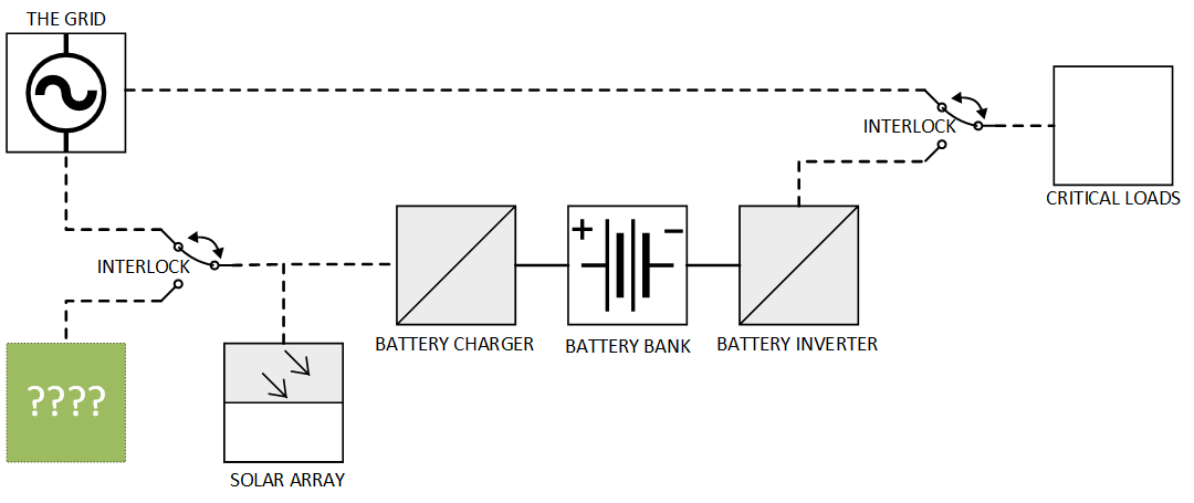
Existing system

It sounds like your (hypothetical?) system currently looks like this (dashed lines for ac, solid for dc):

Existing system

Are you imagining that "????" is some sort of device that would provide an AC signal to "fool" the inverters into thinking they're seeing an ac signal?

The problem -- you have grid-tied (or grid-following) inverters

The inverters you have are grid-tied inverters. Not only are they required by UL 1741 to stop supplying power when the grid signal disappears, they are technically unable to do otherwise. Consider that you have multiple string inverters. When there's an outage, they wouldn't all detect this simultaneously -- so at least one should continue producing 60 Hz -- in theory, this should be enough to provide a 60 Hz signal for the rest. So why doesn't it work?

The grid provides a "stiff" signal. Short of substations, power plants, or large industrial facilities going offline, load and supply changes will not move the frequency by much. This is fundamental to the droop control algorithm that governs the grid. A large or fast shift in the frequency indicates that an outage is imminent, because the grid is moving outside of the range under which droop control can manage loads and sources.

Grid-tie inverters use phase-locked loop (PLL) control to match the frequency and phase of their output signal to what they detect on the grid. Normally, the grid-tied inverters are following the grid signal, but they're also causing changes of their own. With the grid present, these changes are barely perceptible (ripples in an ocean). But if the grid is absent, the changes that each inverter implements will have a greater effect (ripples in a teacup), causing cascading fluctuations which feed back to the input of each inverter. If this frequency is changing too fast, the PLL will become unstable and the inverter will shut down. The UL 1741 limits* are programmed into the inverters before they reach this technical limit, but either way, if the input ac signal starts fluctuating too quickly, the inverters will shut down.

There are two potential solutions to this problem, but either one will may require new microinverters.

Solution one: off-grid inverters with communication

Off-grid inverters, that you'd use for a camper, boat, or remote cabin, develop and sustain their own 60 Hz signal. There's a chance you could install a single off-grid inverter in your system (perhaps at the ???? location, drawing off the battery bank), and the grid-tied inverters would be fooled into following it.

However, there are two potential issues:

  1. The signal probably won't be "stiff" enough. Standard off-grid inverters aren't designed to work in tandem with grid-tied inverters, so the signal they provide is unlikely to be stiff enough to "fool" them.
  2. Grid-tied inverters are current sources and could cause runaway voltage without sufficient load. Standard grid-tied inverters are designed to push a steady current out by raising their output voltage. When connected to the grid, there's a huge sink for this current, so they don't have to raise the voltage much at all. But in an off-grid situation, if they "run out" of load -- the batteries are charged and no one is around using any power -- they might increase the voltage until something breaks, or a safety mechanism kicks in and shuts it off.

One way around these problems is with a communication interface between inverters. In your case, that would probably mean replacing all of your microinverters, since the communication protocol is not yet standardized and tends to be proprietary (and microinverters are unlikely to have any sort of communication interface).

The Sunny Island inverter from SMA is an example of an off-grid inverter that can do this with other SMA inverters. You can see the communication interface in the diagram below:

SMA Sunny Island example configuration

Solution two: an ac-coupled system with a grid-forming inverter

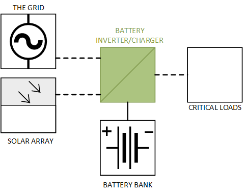
Another option is to re-wire your system as an ac-coupled system, which centralizes the inverter, charger, and grid disconnect, eliminating the need for a communication interface:

ac-coupled system

In this case, you would utilize a battery inverter/charger that is designed specifically for this application. (Schneider electric and Outback Power are the first two I found where I could easily confirm they work in this fashion, but there are probably many others.)

In this solution, the inverter/charger can draw from the grid, the batteries, or the solar array, and supply power to the loads, or back to the grid. When the UL 1741 limits kick in, it disconnects from the grid, but continues drawing power from the PV array or the batteries to supply load. It is designed to produce an ac signal sufficient to operate grid-tied inverters, as long as they're rated to operate in an ac-coupled system (meaning their voltage output is limited).

Some inverter/chargers can handle the grid disconnect/reconnect seamlessly, and essentially constitute a microgrid -- with others, there may be a slight delay before they continue supplying loads, and are more like hybrid solar/backup power systems.

Some microinverters (like Enphase) are specifically rated for ac-coupled systems, but may still require some communication hardware to make this work.

Further reading

Some resources I found helpful when pulling all of this together:


*I don't have UL1741 handy, but IEEE 1547-2018 mirrors it, and gives these ranges as default settings -- there are situations where an inverter can stay connected outside of these ranges, depending on utility interconnect agreements:

Frequency (Hz) Clearing time (s)
62.0 0.16
61.2 300.0
58.5 300.0
56.5 0.16